Editorials
from Cabling-Design.com
|
|
|
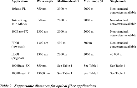
Today's cabling environment is characterized with rapid developments in fiber cabling technology. Some of them are very important for IT managers willing to have a future-proof and cost-effective fiber infrastructure. Traditionally, the American market has been using 62.5 �m multimode fiber in premises cabling systems for many years. The TIA/EIA-568-A "Commercial Building Telecommunications Cabling Standard" standard fully accepts this fiber type and promotes its use. In contrast, 50 �m multimode fiber has had a limited market, was not mentioned in the 568A standard and, therefore, has not been widely accepted in the USA. The reason for not mentioning 50 �m fiber was simple. For almost all fiber network applications existing until recently, it did not matter in terms of performance which multimode fiber core size was used. Both multimode fiber types supported the needed bit rates for the same distances (see Table 2). Gigabit Ethernet changed the situation dramatically. Using lasers and less expensive VCSELs (Vertical Cavity Surface Emitting Laser), Gigabit Ethernet is different from slower applications using Light Emitting Diodes (LEDs). During the development phase, it was discovered that 62.5 �m and 50 �m fibers behave differently transmitting Gigabit streams generated by lasers and VCSELs. As it can be seen from the Table 1, standard 62.5 �m multimode fibers support lesser distances compared to 50 �m fibers. Another blow to the dominance of "normal" 62.5 �m fiber came from the ongoing development of 10 Gigabit Ethernet. This application will be supported only by 50 �m specialized high-bandwidth fiber.
Additionally complicating the issue, some fiber manufacturers (Lucent, Corning) developed enhanced high-bandwidth 62.5 �m multimode fiber solutions for supporting Gigabit Ethernet up to 550 m and more. So, how would you proceed when choosing a fiber type for your next project? Think not about fiber sizes. Instead, use "back to basics" approach and think about network requirements, applications requirements and distances to be covered. I recommend the following decision-making and design procedure: * Step 1. Establish your data transmission
requirements for today and nearest future: * Step 2. Define additional requirements: * Step 3. Choose the network application satisfying your data transmission and additional requirements (see Table 2)
* Step 4. Based on the network application
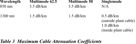
selected, choose the required fiber type. Bandwidth Attenuation * Step 5. Calculate the Channel Attenuation for the worst-case cabling channels Channel Attenuation = cable
attenuation + connector attenuation + splice attenuation You can take the cable attenuation coefficients from the cable manufacturer's datasheet. If it's not available, use the maximum cable attenuation coefficients from the draft ANSI/TIA/EIA-568B standard specified in the Table 3.
You can take the connector pair attenuation from the connector manufacturer's datasheet. If it's not available, use the maximum connector attenuation from the draft ANSI/TIA/EIA-568B standard (0.75 dB per each connector pair). You can take the splice attenuation from the splice manufacturer's datasheet. If it's not available, use the maximum splice attenuation from the draft ANSI/TIA/EIA-568B standard (0.3 dB per each mechanical or fusion splice). * Step 6. Verify that maximum channel attenuation is within the network application limits from Tables 1 and 2
|
|

Choosing the Right Fiber


Home Cabling Guide
Finally, an instantly downloadable book that saves you thousands in home improvement dollars! Enjoy living in 21st century technology-advanced home while increasing its selling value and competitive advantage on the real estate market. Whether your cabling is for home office or high-tech leisure, you can wire your home yourself or learn "wirish" to speak with your cabling contractors in their language!